Antennas are present everywhere around us.
With the advent of 5G, antennas will be present more in number around us.
Every product maker today, will think of incorporating an antenna system in his product. But, testing an antenna is an expensive affair and requires a special environment.
Antenna testing techniques ensure that the antenna meets specifications and specific parameters which are tested are gain, bandwidth, radiation pattern, beam width, polarization, and impedance.’
An antenna is mainly used as a metallic device for radiating or receiving radio waves which is basically used for transmitting signals, transmitting antenna is used to transmit information and for receiving signal, receiving antenna is used at receiver end to receive signals.
MS Ramaiah College of Engineering, Department of Electronics, Headed by Dr. B.K. Sujatha, has recognized this urgent need and established a Centre for Antennas and Radio Frequency Systems.
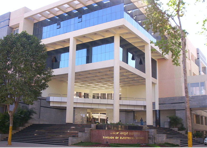
Located in the heart of Bengaluru, very near to IISc and BEL, this Centre is a go to place for getting their antennas tested,
All types of Antennas can be tested.
Industries are encouraged to make use of the expertise offered here to develop their products.
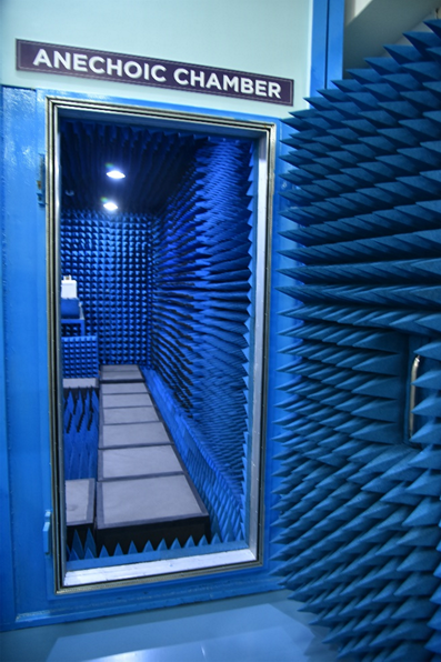
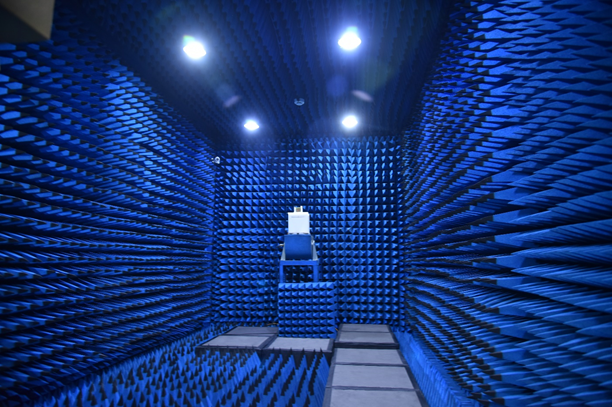
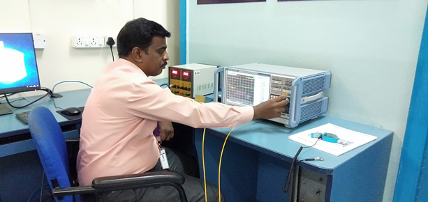
Shielded anechoic chambers are widely used to provide RF isolated test regions to stimulate free-space test environment for measuring antennae. The anechoic chamber provides a controlled environment not subjected to weather and ambient conditions. Anechoic chambers are widely used to measure antennas that are deployed in various telecommunication links, remote sensing, and radar signature measurements. The properties of the chamber were studied from a point of view quiet zone for antenna. The total power budget of reflections, losses and penetration of electromagnetic energy in an anechoic and EMC chamber were taken into account for quiet zone calculation depending on frequency, final arrangement (instruments, test sites, polarization etc.) Measurements that could be carried out in Anechoic Chamber are 2D and 3D radiation patterns, Gain, Polarization, Axial Ratio, Impedance, and VSWR.
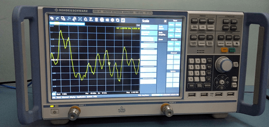
A vector network analyzer or VNA is an instrument that measures the frequency response of a component or a network composed of many components, which can be both passive and active. A VNA measures the power of a high-speed signal going into and coming back from a component or a network, because power, in contrast to voltage and current, can be measured accurately at high frequencies. Both amplitude and phase of the high-frequency signal are captured at each frequency point. The built-in computer in the VNA calculates key parameters such as return loss and insertion loss of the network under test. It is also capable of visualizing the results in different formats—for example, real/imaginary, magnitude/phase, Smith chart, etc. In high-speed system tests, VNA is often used to characterize multi-port networks consisting of components such as connectors, filters, amplifiers, and transmission line/coaxial channels.
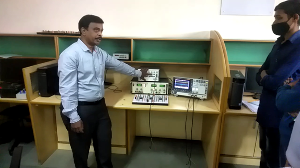
Let me now introduce, Mr. Premnath, Instructor, Centre for Antennas and Radio Frequency Systems, Department of Electronics
To successfully test your antenna you need a good experienced person with a strong theory and practical background. Mr. Premnath, brings to the table this combination and a willingness to learn and work with your project. He will help you in,
- Fabricating Patch Antenna
- Soldering/Drilling Substrates for Mounting SMA Connectors on Antennas
- Fixing the (DUT) Device under Test in an Anechoic chamber
- Fixing same frequency Antenna on Transmitting side
- Connecting SMA Connector to Vector Network Analyzer
- Checking 3 Axis Motor controlled with microcontroller for rotating the DUT in Azimuth and Elevation direction.
- Operate the PC for Commanding VNA as well as Controller to operate DUT it will give results
- Save the file it contains Linear/Polar graph and readings Excel format and send it to Clients
- Frequently checking the Absorber in Anechoic chamber for the long life
Companies/Institutions which can or have utilize this Centre
| Company | Website |
|---|---|
| Bharat Electronics | Bharat Electronics Limited (BEL) is a Navratna PSU |
| AVgarde Systems Pvt Ltd, | Avgarde – Synergising Technology Evolution (avgardesystems.com) |
| Technilab | Technilab.in |
| Elena Geo Systems | Elena Geo Systems |
| Adichunchangiri Institute of Technology, Chickmagalur | Adichunchanagiri University – Excellence, Empowerment, Enlightenment (acu.edu.in) |
| Nitte Meenakshi Institute of Technology | NITTE |
| Government Engineering College, Hassan | Government Engineering College,Hassan | gechassan.ac.in |
| Government Engineering College, Gujarat | GOVERNMENT ENGINEERING COLLEGE, GANDHINAGAR (cteguj.in) |
| Government College of Engineering, Salem | GCE – Salem | Gcesalem |
| IISc, Bangalore | Indian Institute of Science (iisc.ac.in) |
Given the expertise available in the department, companies can avail additional services in the department.
Mr. Premnath, is probably one of the few Instructors in Engineering Colleges in India, who is credited with a Patent Application Pending, details of which are given below.
Title: “A Liquid Antenna System for Transmitting and Receiving Electromagnetic wave”
Patent application no: 202141005075
Inventors: Swetha Amit, Viswanath Talasila, Premnath P M
Applicant: M.S. Ramaiah Institute of Technology
Brief of the Pending Patent
- The antenna can be configured in many shapes; cylindrical shape liquid antenna, half
- loop quarter-wave antenna, miniaturized sea water antenna with impedance matching, free flow returnable liquid antenna system.
- The basic liquid antenna system consists of a pipe to hold saline water, probe, RF connector, transmitter/receiver. For the designed shape of the antenna, the required concentration of saline water depending on application is filled which functions as antenna system thereby, effectively capable to transmit and receive electromagnetic signals.
- The height of the saline water antenna depends on the frequency of operation. The pipe is filled with the required level of saline water to operate for the designed application. The width of the pipe can be chosen depending on the bandwidth constraints. Wider the pipe, more will be the bandwidth coverage. This also impacts the impedance of the antenna also. For a better impedance matching of the antenna system to the other transmitter and receiver circuit, different shapes of feeding probe are designed to optimize the transmission of electromagnetic waves. The width of the water stream can be of any shape, not circular always.
- The behavior of saline water concentration differs with frequency. This novel observation of the effect of saline water to frequency which can be used as a radiating element opened many ways of choosing the optimal density of saline water for the required frequency of communication. An infinite ground plane is constructed with metal rods. A dielectric material is kept in between saline water antenna and to the ground to differentiate the antenna and ground plane. RF connectors are chosen according to frequency of operation.
- The infinite ground plane includes a conducting plate and rods to act as an infinite ground lane as well as a stand to support the antenna. This setup is connected to the transmitter/ receiver for transmitting and receiving electromagnetic waves.
When asked about his goals this was his reply:
- Utilizing My skills towards the professional growth of the Institution in a challenging and competitive work environment
- To upgrade my skills suitable to the current technologies.
- To share the knowledge acquired in a beneficial manner to the student community
Impressive. In the first sentence he has highlighted that Engineering Colleges today exist in a competitive environment. In the second, and third points, he has set his own goals, upgrade continuously and spread. Ideal recipe for success.
When asked what does he think of his students he had an fully optimistic view:
The students in the current decade have more access to technology right from the pre-school level. They observe and analyze in a more detailed manner than we could ever imagine. They handle the software tools with more ease. With a little guidance, they could achieve national goals easily.
I am truly impressed with his observation that students are able to analyze in a detailed manner. Which is true and relevant.
When asked about teaching trends he said:
The conventional black board teaching is now changed to more of digital platform where we use flipped class rooms, pre-recorded lectures and live streaming to remote locations even. Also, there is a tremendous change observed in the curriculum of both undergraduate and post graduate courses, to make the student reach the industry goals with the minimal training after recruitment. AICTE should note this.
Below are the different types of antennas which are designed and developed in the Centre
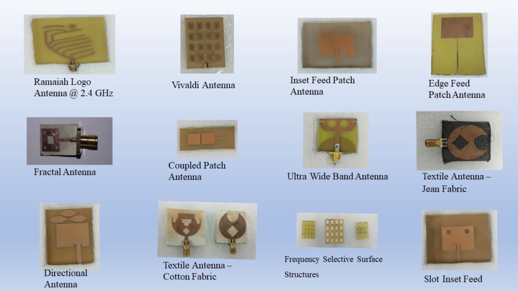
It is evident that the applications are varied and impactful.
Every student has to be exposed to this activity to fire up their imagination.
Additional responsibility in the Lab
In this Laboratory I am involved in fabricating Micro Strip Patch Antennas, basically the Students of UG/PG use a EM Software Tool called HFSS (High Frequency System Simulation) as a part of their academic Projects/Research work. After design and simulation, I take upon for making a physical structure of the antenna. During their designing of antennas, I will help them to bring it to exact structure from a simple substrate to the final Antenna prototype.
Mr. Premnath adds with respect and pride:
Head of the Department – Dr. B K Sujatha is very supportive and encourages with all aspects of career growth as well as the department growth. She identifies the skills of a person in an efficient manner and utilizes them in a proper way.
It is remarkable, that a quiet revolution is happening in India. Support Infrastructure for startups is being created in Engineering colleges. This will greatly enhance the potential of students to explore and create startups.
Good Luck to Mr. Premnath.

Hi Team,
Need to know following answers
1. What’s is Edge Feed antenna
2. Difference between Inset and Edge antenna
Hello Mr. Sheth
Thanks for your comments
In Edge feed antenna, there is no perfect matching between the transmission line and the patch impedance because of which more amount of power will be reflected back as a result of which VSWR value would be high.
To improve the impedance matching between the transmission line and the patch, we go for another type of feed called inset feed, where in the power accepted by the antenna would be more because of perfect impedance matching and hence VSWR would be low
A Liquid Antenna System for Transmitting and Receiving Electromagnetic wave… This is really an intresting topic in the antenna domain.
Great work sir.
Congratulations.
Congrats sir!
Your knowledge in the domain and the way you share your knowledge with your students is incredible. Thanks and wish you reach greater heights.
Dear Mr. Premnath,
I am really impressed with your work , best of luck for your future endeavours. Please keep up the good work .
Thank you.
G.kannan
Congratulations sir..
I think it’s the most happiest moment for you. Coz we have seen you the amount of work and dedication you have put in that.
wish you reach greater heights sir
Good to know.